
What Is the Difference Between C-rate and Power-rate in Energy Storage Systems?
In modern commercial and industrial energy storage systems (ESS), achieving high system-level power output does not necessarily mean stressing individual battery cells. By carefully decoupling C-rate (cell-level charge/discharge speed) from system power-rate (P-rate), engineers can design 0.5P energy storage systems where each cell operates at only 0.25–0.3C. This approach improves battery lifetime, enhances SOC drift control, and ensures safer, more reliable ESS operation. This article explores the key principles, system design strategies, and engineering benefits of this low C-rate, high P-rate methodology.
What Is C-rate in an Energy Storage System?
C-rate is a battery-level parameter that measures how fast a battery cell charges or discharges relative to its rated capacity. For example, 1C corresponds to a full charge or discharge in one hour, 0.5C takes two hours, and 0.25C lasts four hours. In energy storage projects, battery C-rate reflects the intrinsic electrochemical capability of the cell, determined by electrode design, internal resistance, thermal behavior, and material stability. Importantly, C-rate is defined at the cell or module level, not at the system level, which allows engineers to operate cells gently while delivering high system output.
What Is Power-rate (P-rate) in Energy Storage Systems?
While C-rate describes individual cells, power-rate (P-rate) measures system-level energy delivery. It is calculated as:

A 0.5P energy storage system can discharge its rated energy in approximately two hours. Factors determining system power-rate include battery pack configuration, PCS rated power, DC bus voltage, and BMS/EMS control strategies. Unlike C-rate, power-rate reflects system output, not the stress on individual cells.
What Is C-rate in Energy Storage Systems?
While C-rate is traditionally a cell-level metric, it can also be interpreted at the system level to understand how much stress each cell experiences relative to the system’s total energy output. The effective system C-rate can be calculated as:

Where:
System Current = total current drawn from the battery pack
Total Cell Capacity = sum of capacities of all parallel-connected cells
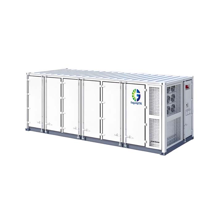
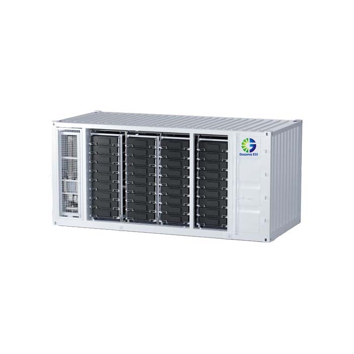
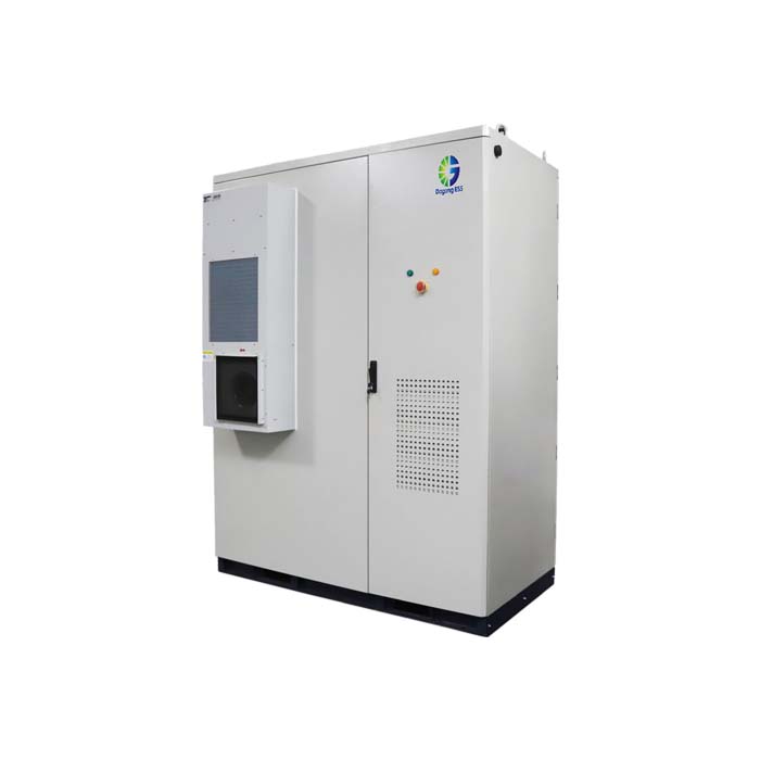
For example, in a 0.5P energy storage system with 215 kWh energy capacity and 107.5 kW rated power (as in Dagong ESS 215kWh Air-Cooled Commercial & Industrial ESS):

However, if the system uses multiple parallel cells, the actual C-rate per cell is reduced because the total current is distributed across more cells:

This demonstrates that even at high system P-rate, individual cells can operate gently at a low C-rate, improving battery lifetime, SOC stability, and safety. For example, in the Dagong ESS 5MWh Liquid-Cooled ESS Container, the system delivers high output power while keeping single-cell C-rate low, supporting long-term reliable operation—an essential design principle for commercial and industrial ESS.
Why C-rate and Power-rate Are Often Confused
Many discussions incorrectly equate C-rate with power-rate, leading to claims like “a 0.5P system operates at 0.5C.” In reality, a well-engineered ESS can deliver 0.5P output while battery cells operate at a lower C-rate, typically 0.25–0.3C. Recognizing this distinction is key for commercial and industrial ESS, where longevity, reliability, and safety are priorities.
How a 0.5P Energy Storage System Achieves Low C-rate Operation
Consider a 215 kWh system delivering 107.5 kW, achieving 0.5P system power-rate. By increasing the number of cells connected in parallel, the total current is distributed, reducing the working C-rate per cell to approximately 0.25–0.3C. This low C-rate battery design allows the system to meet performance targets while:
Extending battery life to 8000+ cycles
Supporting 15+ years of service life
Reducing long-term capacity fade
This demonstrates that high system-level power does not require aggressive stress on individual battery cells.
How Low C-rate Operation Improves Battery Lifetime and SOC Stability
Operating cells at lower C-rates reduces electrochemical stress, including polarization voltage and internal heat generation, slowing material degradation and SEI layer growth. Additionally, low C-rate operation improves SOC drift control—the mismatch between estimated and actual state-of-charge—by minimizing measurement errors, voltage deviations, and polarization effects. As a result, the BMS can maintain better module balance and system capacity over time, which is especially important in large-scale commercial and industrial ESS.
Safety Advantages of Low C-rate System Design
Low C-rate operation also enhances safety. Cells operating at 0.25–0.3C experience lower temperature rise, improved thermal uniformity, and reduced risk of thermal propagation. This strategy aligns with UL 9540 and UL 9540A standards, making it ideal for large-scale commercial and industrial ESS installations where safety and reliability are critical.
Why Modern Commercial and Industrial ESS Favor High P-rate with Low C-rate Cells
In most C&I ESS applications, the design priority is long-term reliability, predictable performance, and low maintenance cost rather than peak power density. By decoupling system power-rate from cell C-rate, modern ESS achieve:
High system output (high P)
Gentle cell operating conditions (low C)
Extended battery lifetime and reduced capacity fade
Cost-efficient operation and stable grid interaction
This “high P, low C” philosophy has become a mainstream design approach for commercial and industrial energy storage projects worldwide.
Key Engineering Takeaways
C-rate measures cell-level operation speed
Power-rate defines system-level energy delivery
Mature ESS designs intentionally keep cell C-rate lower than system P-rate
High-quality ESS are built around 0.5P output with 0.25–0.3C cell C-rate
Understanding the difference between C-rate and power-rate is essential for evaluating ESS performance. A 0.5P energy storage system does not require battery cells to operate at 0.5C; through intelligent system design, cells can work at 0.25–0.3C, achieving improved battery lifetime, SOC stability, and safety. This approach is widely adopted in modern commercial and industrial energy storage systems, delivering reliable and efficient solutions.
If you are interested in energy storage system solutions, please contact Dagong ESS
📧 Email: sales@dagongess.com
🌐 Website: www.dagongess.com